
Location -> Products -> Flow -> Flow Switch
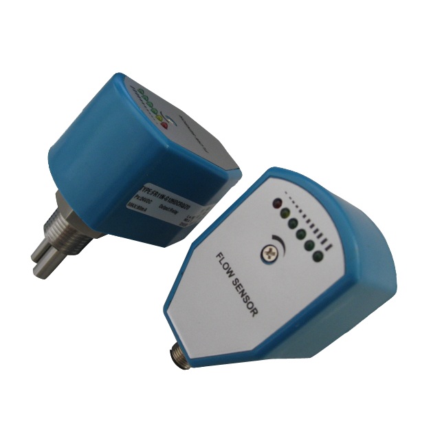
Type£º CX-FS-FR11 electronic flow sensor (thermal differential type)
Illustrate£ºCX-FS-FR11 electronic flow sensor (thermal differential type) can be uesd to control flow.
CX-FS-FR11 Electronic flow sensor (Thermal differential type)
1.Suitable for the gas and liquid measurement
2.The set range can be 1-20m/s and have relay output (230VAC.4A).
3.Concise and direct indicator ,and with high reliable
4.Widely used in pneumatic and hydraulic systems, flow monitoring for recycled water, cutting fluid and lubricating oil , the protection of pump’s run idle
Main Features
1.No movable parts
2.Maintenance free and Easy installation
3.Suitable for variable diameter demand
4.Switching value can be adjusted continuously
5.Extremely low pressure loss
6.Compact structure
7.LED indicator display flow trend and switch state
Technical parameters
| Set range | 1…150cm/s( water),3…300cm/s(oil),20…2000cm/s(air) |
| Output | PNP, NPN, Relay ,4-20mA, NO+NC (SPDT) |
| Power supply | 24V±20%DC or 230V±15%AC |
| Switching Current | Max.400mA(PNP or NPN type ), Max.4A( Relay type ) |
| Unload current | Max.80mA |
| Flow indicator | LED (6) |
| Set type | potentiometer set |
| Proof Pressure range | 100bar |
| Temperature gradient | 4¡æ/s |
| Response time | 1--13s,standard is 2s |
| Initialization time | 8s |
| Electrical protection | reversed-phase ,short circuit ,overload protection |
| Protection class | IP67 |
| Medium temperature | 20--80¡æ |
| Environment temperature | -20--80¡æ |
| Storage temperature | -20--100¡æ |
| Connection | M12 connector /2m cable (option) |
| Material | Probe is stainless steel . Housing is PBT |
| Weight | 0.4kg |
Model
| Model | Connection | Power | Output |
| CX-FS-FR11-G12H-DA-Q | G1/2 | DC24V | 4-20mA |
| CX-FS-FR11-G12H-DC-RQ | G1/2 | DC24V | Relay |
| CX-FS-FR11-G12H-WC-RC | G1/2 | AC220V | Relay |
Dimension .
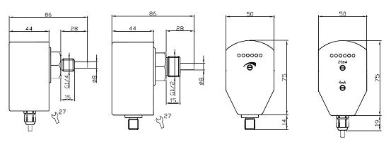
| G1/4 Screw | G1/2 Screw | Switch output | Analog output |
Installation
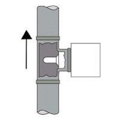
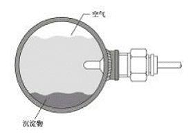
When mounted vertically , it should install on the tube which flow direction is from the bottom to the top . When mounted horizontally , the probe should avoid air and sediment .
Electric connection
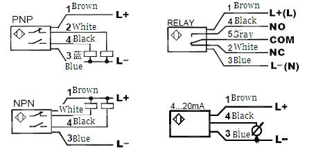
LED functions and setup ( switch type )
Red LED light: If the cutting flow or velocity is less than the set value. The switch will be release and the analog value will be 4mA .
Yellow LED light: If velocity equal to the set value ,switch action .
Yellow and green LED light :It means that velocity is larger than set value. If the velocity will be faster ,the green LED will be lighter ,
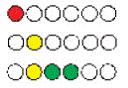
Installed the flow switch well ,let the velocity suit for monitoring and adjust the potentiometer .Let the first the green LEC just turn light . Then, after the velocity less than the current value , the switch will be released . To make the switch point less than the current velocity , it can adjust the potentiometer and make the green LED lighter .
LED function and setup ( analog output type )
Analog output type flow sensor , the output is 4-20Ma . It is proportional to the velocity ,the output belong to nonlinear . There are two knobs for each sensor , one is upper (20Ma) and ther other is (4Ma ) ,which used to output setup .
Red LED light : The flow range is less than the lower limit . Output <4Ma
Green LED light : The flow range is in the set range . 4mA<output<20mA¡£
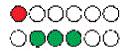
Installed the flow sensor well ,let the velocity suit for monitoring but with lower velocity ,adjust the lower knob and let the first green LED light (4Ma) . Let the velocity suit for monitoring but with upper velocity ,adjust the upper knob and let the fifth green LED light (20Ma) . Since then , the output is proportional to the velocity between upper and lower velocity ; It means that 4Ma corresponds to lower velocity and 20mA corresponds to upper velocity .
Last£º CX-FS-FR12 electronic flow swi.. Next£ºCX-FS-FPD20 pointer display typ..